
From Grid Beams to Joist Bays: A New Area-Assignment Workflow in Linkoteq
Linkoteq’s 3D Model now includes code for area-based and two-point steel joist layout, with a recent fix for rectangular bays formed by continuous grid beams. Here is what is implemented—and what still needs validation.
Why joist layout needs more than a line tool
In structural modeling, repetitive framing can be deceptively time-consuming. A joist may be represented as a line between supports, but a floor bay often contains many parallel joists at a consistent spacing. Placing each member separately introduces avoidable work and makes it harder to review whether the intended framing pattern matches the supporting beams. The engineering challenge is not simply drawing lines: the software must interpret the bay boundary, choose the correct support direction, and preserve a meaningful joist designation without overstating analytical capabilities.
Two workflows for different modeling tasks
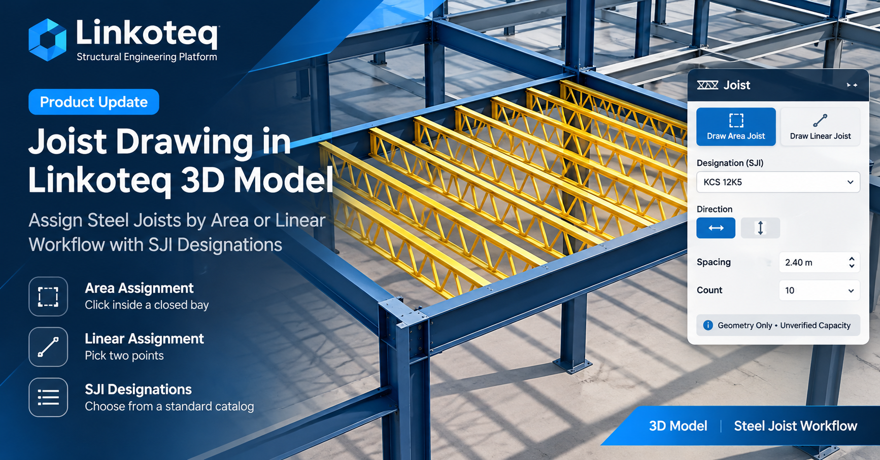
Recent changes in Linkoteq’s 3D Model repository introduce two distinct joist assignment paths in the Advanced Model editor. In Area Assignment, the user selects a point inside a closed four-sided beam-framed bay and previews a joist layout. The controls support a direction and either a member count or a spacing input. In Two-Point Assignment, the user selects the first and second endpoints of a single joist. These are complementary workflows: area assignment addresses repetitive bay framing, while two-point assignment remains useful for isolated or nonstandard locations. The code includes separate drawing actions and a first/second-point state for the linear method.
What changed in the November 1 bay-detection fix
The latest inspected commit, adds a fallback for rectangular plan-grid bays. It searches for the nearest framing lines on each side of the clicked point, then checks that beam segments cover all four boundaries. This matters because visible grid cells are not always modeled as four separate beam objects: a beam may run continuously across several bays. Earlier code also splits crossing and intersecting beam geometry into candidate edges before tracing enclosed faces. The fallback is deliberately constrained to axis-aligned rectangular bays; it should not be interpreted as proof that every irregular, skewed, or curved framing arrangement is supported.
A transparent distinction between geometry and capacity
A steel joist designation is useful identification, not a substitute for verified design properties. The current editor presents reference designations sourced from published SJI material, while explicitly describing the joist capacity as unverified. That distinction is important. A geometry-only joist can support visual coordination and preliminary layout, but it does not establish a safe span, allowable load, deflection performance, vibration behavior, or code compliance. Engineers must check the actual joist manufacturer’s current tables, load criteria, bridging and bearing requirements, and the applicable project specifications before relying on a selection.
A practical example: a rectangular framed bay
Consider a rectangular floor bay bounded by beams along two grid lines in each direction. The user selects the Area Joist action, chooses a reference designation, and clicks inside the bay in plan view. The application attempts to identify four enclosing support boundaries. If it finds an unambiguous bay, the user can choose the spanning direction and specify a joist count or spacing for preview. The layout algorithm distributes the lines across the selected opposing edges. This is a description of the implemented code path, not a claim that every project configuration has passed interactive acceptance testing.
What an engineer should verify in the model
A useful review starts with the support geometry. Confirm that the selected bay is the intended level and that all four framing boundaries exist. Check whether the joists run between the intended supports rather than parallel to them. Inspect the count and spacing, especially near edges where the layout may not match fabrication requirements. Review each joist designation and any stored properties independently of the visual appearance. For an imported or edited model, also check that member identifiers, elevations, local axes, end releases, and model persistence remain consistent after saving and reopening. Geometry visible on screen is not, by itself, proof of analytical connectivity or correct end conditions.
What the available evidence actually confirms
The November 1 GitHub history documents the introduction of area and two-point assignment, user-interface refinements, and a rectangular-bay detection fix. A corresponding production deployment for commit bded33e was reported READY by Vercel. READY establishes that the deployment completed successfully; it does not demonstrate that all interactions work across browsers or that model persistence and structural analysis are validated. This article therefore describes a shipped code and deployment milestone, not a completed engineering certification or a fully verified end-to-end test.
Current boundaries and next validation steps
The immediate validation priorities are straightforward: test rectangular bays with separate and continuous beams; test intersecting grids, partial boundaries, and invalid or ambiguous cells; verify point picking and zoom in plan view; confirm count and spacing inputs; and save and reopen models containing joists. Engineering checks should also verify that geometry-only joists remain clearly labeled as unverified and do not silently inherit fictitious analytical sections. The same transparency should apply to future structural analysis integration: only verified mappings and results should be presented as design evidence.
Why this matters for structural workflows
A good modeling tool should reduce repetitive interaction without hiding engineering assumptions. Bay-based joist assignment is a small but meaningful step toward that goal. The opportunity is faster preliminary framing and clearer model coordination; the responsibility is to keep the distinction between modeled geometry and validated design unmistakable. Linkoteq will continue to treat that boundary as part of the feature, not as a footnote.
Evidence and further reading